


7S 24V 20A Li-ion Lithium 18650 Artikelnummer: 366120
Zitat von h.wind am 17. September 2020, 13:37 UhrGuten Tag, wo finde ich denn den Schaltplan, wie ich dieses Teil anzulöten habe?
Wo werden die 7 dünnen Kabel angelötet? An den Fahnen der Akkus, klar, ist eine bestimmte Reihenfolge notwendig oder ist das egal?
Und wo kommen die dicken Kabel dran? Ich habe da (Stecker links) oben einen dicken Lötpunkt mit "P-" und unten einen Lötpunkt mit "Bat-" 2 x Minuspol???
Im defekten BMS sind 4 Lötpunkte für die Kabel.
Guten Tag, wo finde ich denn den Schaltplan, wie ich dieses Teil anzulöten habe?
Wo werden die 7 dünnen Kabel angelötet? An den Fahnen der Akkus, klar, ist eine bestimmte Reihenfolge notwendig oder ist das egal?
Und wo kommen die dicken Kabel dran? Ich habe da (Stecker links) oben einen dicken Lötpunkt mit "P-" und unten einen Lötpunkt mit "Bat-" 2 x Minuspol???
Im defekten BMS sind 4 Lötpunkte für die Kabel.
Hochgeladene Dateien: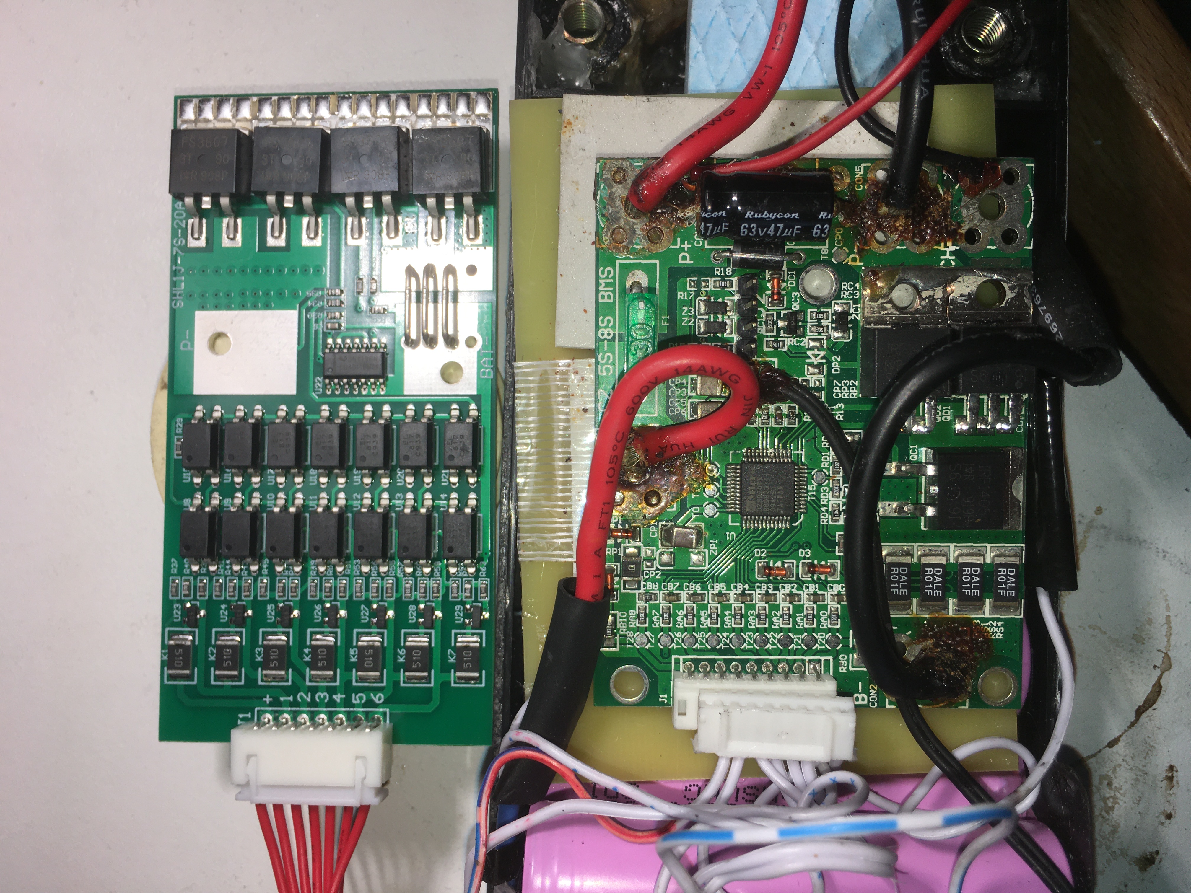
Zitat von hansjoerg.gehring am 22. September 2020, 17:32 UhrIch habe das gleiche BMS gekauft und raetzel auch gerade wo ich was anschliesse.
Wie ich die einzelnen Zellen anschliesse ist klar. Das sieht man beim Produkt in der Bildergalarie. Aber wo kommt der Verbraucher (ebike motor) ran und wo das Ladegerät fuer mein EBike?
Der Minuspol der untersten der 7s Zellen kommt an BAT-. Der pluspol der ersten Zelle (4.2V) an position 6 am stecker. Der Pluspol der obersten Zelle am pin+ des steckers erscheint mir zu duenn fuer 20Ampere. Wo greife ich also Bat+ 24V 20A ab? Vermutlich ist P+ (Power plus) die Loetleiste, gegenüber von der Steckerseite. Und ist P- fuers laden der akkus also den Anschluss des Ladegeraets gedacht oder B-? In der Bildergalarie ist der Anschluss als Pack bezeichnet.
Ich habe das gleiche BMS gekauft und raetzel auch gerade wo ich was anschliesse.
Wie ich die einzelnen Zellen anschliesse ist klar. Das sieht man beim Produkt in der Bildergalarie. Aber wo kommt der Verbraucher (ebike motor) ran und wo das Ladegerät fuer mein EBike?
Der Minuspol der untersten der 7s Zellen kommt an BAT-. Der pluspol der ersten Zelle (4.2V) an position 6 am stecker. Der Pluspol der obersten Zelle am pin+ des steckers erscheint mir zu duenn fuer 20Ampere. Wo greife ich also Bat+ 24V 20A ab? Vermutlich ist P+ (Power plus) die Loetleiste, gegenüber von der Steckerseite. Und ist P- fuers laden der akkus also den Anschluss des Ladegeraets gedacht oder B-? In der Bildergalarie ist der Anschluss als Pack bezeichnet.
Zitat von h.wind am 22. September 2020, 19:11 UhrVielen Dank, das hilft schon einmal. Aber noch keine finale Hilfe. Kann man nicht einfach einen Schaltplan online stellen? Seitens des Herstellers natürlich. Ich habe jetzt auch ein BMS nur mit Kabel rein und raus. Ohne die kleinen Kabel zu den Zellen. Ist das denn so viel schlechter? Die Leistung kommt ja eh über die dicken Kabel. Was meint die schweigende Mehrheit hier? Danke vorab!
Vielen Dank, das hilft schon einmal. Aber noch keine finale Hilfe. Kann man nicht einfach einen Schaltplan online stellen? Seitens des Herstellers natürlich. Ich habe jetzt auch ein BMS nur mit Kabel rein und raus. Ohne die kleinen Kabel zu den Zellen. Ist das denn so viel schlechter? Die Leistung kommt ja eh über die dicken Kabel. Was meint die schweigende Mehrheit hier? Danke vorab!
Zitat von h.wind am 22. September 2020, 20:52 UhrHier mal meine neue Platine, die man einstellen kann. Ich werde das mal mit meinen alten Akkus probieren, die vielleicht noch garnicht komplett tot waren, nur das BMS war kaputt.. vermutlich...
Hier mal meine neue Platine, die man einstellen kann. Ich werde das mal mit meinen alten Akkus probieren, die vielleicht noch garnicht komplett tot waren, nur das BMS war kaputt.. vermutlich...
Hochgeladene Dateien:
Zitat von h.wind am 22. September 2020, 21:20 Uhr
Li-ion Akku Laderegler Modul Batterie Lademodul Charging Controller 6-60V 10A DE
Descriptions:
This battery charging controller module, features automatic charging, automatic power off, suitable for battery use of 6V-60V, and use for car generators, solar power, wind turbines, electric vehicles charge.Feature:
- Thick circuit board for long-lasting performance.
- Easy to wire and safe to use. Adjustable parameter and memory retention function.
- Suitable for various storage batteries and lithium batteries.
- Automatic charging and discharging, safe to operate.
- Used for car generators, solar power, wind turbines, electric vehicles charge.
Specification:
Name: Battery Charge Control Module
Control Voltage: 6-60V
Control Current: ≤10A
Control accuracy: 0.1V
Voltage Deviation: ±0.1V
Application: various storage batteries and lithium batteries
Size: Approx. 7*4.8*1.7cm / 2.8*1.9*0.7inch
Weight: 33gVoltage set method:
In the state of normal stage(digital tube flash)
Starting key can turn up the voltage.
Stopping key can turn down the voltage.Set starting voltage:
In the common state of normal voltage display, press the starting key, display the charging starting value voltage.
Long press the starting key until the digital tube flash. Set the charging starting voltage value by starting key and stopping key.Set stopping voltage:
In the common state of normal voltage display, press the stopping key, display the charging stopping voltage.
Long press the stopping key until the digital tube flash. Set the charging stopping voltage value by starting key and stopping key.Resetting:
In the common state of power-on, press the starting key and stopping key simultaneously, digital tube display 888, resetting is successfully completed.Settings:
When the starting value can not be added, please adjust the stop value.Q&A:
Question:
How many voltages are batteries fit?
Answer:
This module is suitable for the voltage range of 6-60V, support 48V batteries maximally. Because the voltage of 48V batteries is about 60V when fully charging. The module will be burned if the voltage is more than that.Question:
Why did the module not display after connecting the charger?
Answer:
Because module can display when it is powered by the battery, not display when the voltage is less than 6V.Question:
The starting voltage is so low or the stop voltage is high.
Answer:
Because the limiting start value is less than the stop value. If you want to adjust the start value, you should adjust the stop the value first, vice versa.Question:
The relay has a sound of flapping. Digital tube or indicator light is flashing.
Answer:
The charging current is too large or the battery capacity is too small. The voltage become the stop value when charging and do the starting value when discharging circularly.
The output voltage of the charger is higher than setting stop voltage value. The voltage become the stop value when charging and the starting value when discharging circularly.
If you do not believe please set the stop voltage value above 60V, use the charger corresponding to the battery, and usually the charging current is 1/10 or 1.5/10. Charging voltage is 1.2 times that of the battery.Question:
What mode can control auto-cycle charge? Can it charge while using?Can the flow be limited ?
Answer:
This is voltage control. For example, set start voltage 12V, stop voltage 14.4V. When the battery charges to 14.4V, it stops charging; when the battery decreases to 12V, it begin to charging.
It can charge while using. Module control mode is only controlled shut off and open, module can not limit flow. The charge current depends entirely on your charger current.Question:
Can 12V battery charge 24V? Or can 48V battery charge 12V?
Answer:
No, module is to detect the battery voltage to control the switch, can't change the voltage to charge the battery. You have to choose the corresponding charger to the corresponding type of charging battery.Package Included:
1 x Charge Control Module
|
Li-ion Akku Laderegler Modul Batterie Lademodul Charging Controller 6-60V 10A DE Descriptions: Feature:
Specification: Voltage set method: Set starting voltage: Set stopping voltage: Resetting: Settings: Q&A: Question: Question: Question: Question: Question: Package Included: |
Zitat von hansjoerg.gehring am 23. September 2020, 11:36 UhrIch habe jetzt mein samsung akku mit 7 Zellen an den Stecker zur Platine angeschlossen. Den Minuspol des Akkupacks direkt mit Bat - auf der platine verbunden. Danach habe ich gemessen ob ich irgendwo 24V erhalte. Eine solche Stelle konnte ich nicht finden. Weder von P- nach Plus am akkupack noch gegen die unbeschriftete Metallzunge gegenüber des Platinensteckers war eine Spannung zu messen. Die 4 grossen Mosfet hatten an einem Beinchen ca. 14 Volt.
Ich weiss jetzt ohne einen Anschluss plan der mir sagt wo ich die 24V Ausgangsspannung und die 29V ladespannung anlege nicht weiter. Das BMS wird dadurch unbrauchbar fuer mich.
Wie bekomme ich hilfe vom Supportteam?
Hallo h. Wind. Du wechelst das thema der ueberschrift. Du schreibst jetzt ueber ein ganz anderes modul. Ich weiß nicht wie das hier hilft?
Ich habe jetzt mein samsung akku mit 7 Zellen an den Stecker zur Platine angeschlossen. Den Minuspol des Akkupacks direkt mit Bat - auf der platine verbunden. Danach habe ich gemessen ob ich irgendwo 24V erhalte. Eine solche Stelle konnte ich nicht finden. Weder von P- nach Plus am akkupack noch gegen die unbeschriftete Metallzunge gegenüber des Platinensteckers war eine Spannung zu messen. Die 4 grossen Mosfet hatten an einem Beinchen ca. 14 Volt.
Ich weiss jetzt ohne einen Anschluss plan der mir sagt wo ich die 24V Ausgangsspannung und die 29V ladespannung anlege nicht weiter. Das BMS wird dadurch unbrauchbar fuer mich.
Wie bekomme ich hilfe vom Supportteam?
Hallo h. Wind. Du wechelst das thema der ueberschrift. Du schreibst jetzt ueber ein ganz anderes modul. Ich weiß nicht wie das hier hilft?
Zitat von h.wind am 4. Oktober 2020, 9:33 UhrNa ja, es hilft insofern, weil es eine Alternative darstellt. Und weil die Platinen millionenfach rausgehauen werden, gibt es auch keinen Support. Also nehme ich eine Alternative. Du sagst ja selber, daß das obige BMS unbrauchbar ist. Da solltest Du Dich über eine Alternative freuen und nicht beklagen. 😉
Na ja, es hilft insofern, weil es eine Alternative darstellt. Und weil die Platinen millionenfach rausgehauen werden, gibt es auch keinen Support. Also nehme ich eine Alternative. Du sagst ja selber, daß das obige BMS unbrauchbar ist. Da solltest Du Dich über eine Alternative freuen und nicht beklagen. 😉
Zitat von hansjoerg.gehring am 5. Oktober 2020, 18:15 UhrHallo h.wind
Es hat bei mir doch noch geklappt. Die 7s Platine funktioniert gut. Mann muss nur wissen dass man sowohl Ladegeräte als auch den Verbraucher an P- bzw. PACK- anschliesst. Der Plus geht direkt zum Akkupack und Batterie minus an Bat. -.
Hallo h.wind
Es hat bei mir doch noch geklappt. Die 7s Platine funktioniert gut. Mann muss nur wissen dass man sowohl Ladegeräte als auch den Verbraucher an P- bzw. PACK- anschliesst. Der Plus geht direkt zum Akkupack und Batterie minus an Bat. -.


