


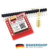
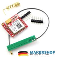
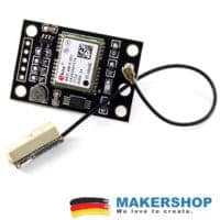
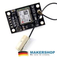
A6 Quad Band GSM Shield SMS GPRS SIM900A
Nicht vorrätig
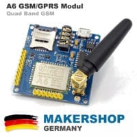
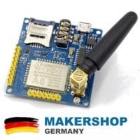
A6 von AiThinker GSM & GPRS Modul ähnlich dem SIM900A zur Nutzung mit Arduino, Raspberry Pi oder anderen Mikrokontrollern.
Die Kommunikation erfolgt über TTL/RS232 Seriell. Mit diesem Modul lassen sich interessante Projekte umsetzen, die per SMS oder GPRS Daten über GSM kommunizieren können.
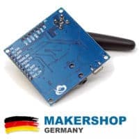
Die Spannungsversorgung erfolgt mit dem integrierten USB Micro Anschluß, welcher nicht für die Kommunikation mit dem Board genutzt wird.Zur Kommunikation, sowie zum Daten – Upload und Downlaod empfiehlt sich unser USB TTL Konverter oder eine direkte Verkabelung mit dem Micro-Kontroller.
Und so funktioniert es:
- USB 2.0 A Stecker USB Micro B Stecker mit Spannung versorgen (im Lieferumfang nicht enthalten)
- USB TTL Konverter (im Lieferumfang nicht enthalten) an Pin U_RXD und U_TXD anschliessen
Übersicht der Funktionen:
- GSM: 850 / 900 / 1800 / 1900MHz
- Betriebsspannung: 4.8-9VDC
- Sleep Current: 5mA
- Onboard Micro SIM
- Onboard Micro USB
- Kommunikation: TTL Seriell / RS232 Seriell
- Baud Rate: 115200bps (AT Befehle)
- Logik Spannung: 3.3V
- Anschluss: Kopfhörer + Mikro
- SMS Senden & Empfangen
- GPRS Senden & Empfangen
- Ai-Thinker GPRS A6 module
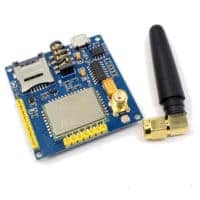
- Onboard Antenne
Arduino Bespiel Code zur Kommunikation per TTL:
char phone_no[]=”+33614687128″;
void setup() {
Serial.begin(9600);
delay(300);
Serial.println(“AT+CMGF=1”);
delay(2000);
Serial.print(“AT+CMGS=””);
Serial.print(phone_no);
Serial.write(0x22);
Serial.write(0x0D); // hex equivalent of Carraige return
Serial.write(0x0A); // hex equivalent of newline
delay(2000);
Serial.print(“GSM A6 test message!”);
delay(500);
Serial.println (char(26));//the ASCII code of the ctrl+z is 26
}
void loop()
{
}
QUAD BAND GSM BOARD FEATURES:
- Working Voltage 3.3V – 4.2V
- Power Voltage 3.4V
- GPIO Level 2.8V
- only 3mA Standby Current
- 2.54 mm Pitch
- Supports Quad Band
800 MHz.
900 MHz.
1800 MHz.
1900 MHz. - GPRS Class 10
- Quad Band Antenna included
- Supports voice calls
- Speaker output
- Microphone input
- Supports digital and analog audio
HR Coding
FR Coding
EFR Coding
AMR Coding - Supports SMS Message
- Supports GPRS Data Service
up to 85.6
kbps Download
up to 42.8 kbps Upload - GPS Location Information Support
- integrated USB Micro Interface for power supply
- 5 GPIO Interface
- 2 UART serial Interface
U_RXD U_TXD serial AT commands
HTXD URXD download Data - AT Command support
GSM 07.07
GSM 07.05 - Supports Standard TCP/IP Commands
- Certification
ROHS Certificate
FCC Certificate
CE Certificate
CTA Certificate
TECHNICAL SPECIFICATION
– dimensions of 22.8 16.8 2.5mm;
– Operating temperature -30 to + 80 ;
– Operating Voltage 3.3V-4.2V;
– Power voltage> 3.4V;
– Standby average current 3ma less;
– support the GSM / GPRS four bands, including 850,900,1800,1900MHZ;
– Sensitivity <-105; – support voice calls; – support SMS text messaging; – Support GPRS data traffic, the maximum data rate, download 85.6Kbps, upload 42.8Kbps; – Supports standard GSM07.07,07.05 AT commands and extended commands Ai Thinker; – supports two serial ports, a serial port to download an AT command port; – command supports the standard AT and TCP / IP command interface; – support digital audio and analog audio support for HR, FR, EFR, AMR speech coding; – Support 2G 3G 4G mobile card Unicom card – support ROHS, FCC, CE, CTA certification; – the SMT 42PIN package; MODULE PIN FLAG: VCC_IN: Power Supply Input 5V -9V GND: power ground U_TXD: A6 module to send (TTL level) U_RXD: A6 receiving module (TTL level) RS232_TX: 232 serial port RS232_RX: 232 serial port to receive HTXD: Serial Interface Upgrade HRXD: Serial Interface Upgrade MIC- MIC +: microphone input REC + REC-: Speaker output INT: Control module is used to enter a low-power mode, high back Out into the low PWR: power button,> 1.9V more than 2s to boot
(Module hardware to do the processing, power is automatically turned on, eliminating the need for wiring trouble)
EN: MP1584 power chip enable pin, pulled enable power chip, low enabled, this pin can be used as module reset pin enable
| Gewicht | 21,00 g |
|---|---|
| Maße | 5 × 5 × 1,9 cm |
Dokumente
5 Rezensionen für A6 Quad Band GSM Shield SMS GPRS SIM900A
Ähnliche Produkte


Martin (Verifizierter Käufer) –
Hi,
I just bought a “A6 Quad Band GSM Shield SMS”. I can’t find any documentation like wiring instruction and basic commands. Would be nice if a link to documentation could be provided.
Thanks
timo –
Hier der Link zur A6 Dokumentation und Befehlsübersicht:
http://www.alselectro.com/files/A6-AT-Commands.pdf
Martin (Verifizierter Käufer) –
Hallo timo, Danke für den link, aber was ich wiirklich brauche ist ein Liste der Pins doie auf dem Borad belegt werden müssen. Bisher habe ich folgendes mit dem Arduino Uno verbunden:
GND => GND (Pin 14)
U_RxD => Tx (Pin 0)
U_TxD => Rx (Pin 1)
Leider bekomme ich kein Antwort vom GSM module. Es leuchtet lediglich die rote LED neben der SIM Karte. Ab und an blinkt ein blaue LED in der Nähe des U_RxD pins. Gibt es ein Beschreibung was die LED’s bedeuten? Sollte sich das Bord auch ohne Arduino ins Funknetz einloggen?
Danke Martin
Martin (Verifizierter Käufer) –
Ich habe natürlich auch eine Spannungssversorgung über den USB micro Anschluß angelegt.
timo –
Hallo. Wir müssten es selber noch mal lokal Prüfen. Bis jetzt hatten wir noch keine negativen Rückmeldungen. Eventuell kann auch dieser Link helfen, insbesondere der letzte Post: https://forum.arduino.cc/index.php?topic=422375.15.
Sollte alles nicht klappen, einfach bitte kurz über das Kontaktformular eine Nachricht senden. Dann können wir eine kostenlose Rückgabe einleiten. Das ist überhaupt kein Problem.
Service ist uns wichtig und wir wollen, dass unsere Kunden zufrieden sind. Probleme möchten wir schnell und kulant im Interesse der Kunden lösen.
Liebe Grüße!